
Page 3 - Crown Head Owners Manual L91v0116v
P. 3
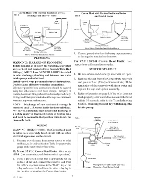
Crown Head  with  Raritan Sanitation Device,         Crown Head with Raritan Sanitation Device
             FIG 2      Holding Tank and “Y” Valve              FIG 3            and Vented Loops

                                                To
                                                Deck
                                              Pumpout                  Vented                     Vented Loop
                                                                       Loop
                  Crown Head                                                  Crown Head
                               “Y” Valve  Holding Tank

                                                                                      Sanitation Device  Discharge
                                                                         Intake                        Thru-Hull
                                                                        Thru-Hull and                  And Seacock
                                                                        Seacock
                             Sanitation Device                                    Drawing Not to Scale
                      Intake                   Discharge                 At or Below Waterline Installation Shown
                      Thru-Hull                Thru-Hull
                     and Seacock               and Seacock
                              Drawing Not to Scale             3.  Connect ground wire from the battery or power source
                       Above Waterline Installation Shown
                              PLUMBING                             to the negative terminal on the motor.

            WARNING:  HAZARD OF FLOODING                       For  VAC  120/240 Crown  Head  Units:    See
            Toilets mounted at or below the waterline, at greatest   instructions with transformer units.
            angle of heel, and connected to a  Seacock/Thru Hull            SYSTEM START-UP
            Fitting(s) MUST have VENTED LOOPS installed
            in toilet discharge plumbing and between raw water   1.  Be sure intake and discharge seacocks are open.
            intake pump and toilet bowl.                       2.   Remove the cap from the Concentrate reservoir
            Install vented loops per manufacturer’s instructions.   and pour in 2 oz. (59ml) of Concentrate; fill the
            Double clamp all below-waterline connections.          remainder of the reservoir with fresh water and
            Whenever possible hose connections should be secured   replace the cap and siphon assembly.
            using two all-stainless steel hose clamps.  Integrity of
            clamps, hoses and fittings should be checked periodically.    3.  Refer to Operation on page 1. If the toilet does not
            Fittings and 90 degree bends should be kept to a minimum   flush properly, or if water does not enter the bowl
            to maintain proper performance.                        within 10 seconds, refer to the Troubleshooting
            NOTE:  Discharge of raw untreated sewage is            Section.  Running the unit dry will damage the
            restricted in all U. S. waters inside the three-mile limit.    intake pump.
            “Y” Valves, if installed, must direct toilet discharge to
            a USCG approved treatment system or holding tank
            and must be secured in that position while inside the   FIG 4       Pushbutton
                                                                                 Switch
            three-mile limit.                                                   (164000BR)   3 Amp Fuse or
                                                                                             Circuit Breaker
                                WIRING                           #14 Awg                      Main Fuse or
                                                                                             Circuit Breaker
            WARNING:  RISK OF FIRE - The Crown Head must         Wire                      (See Specification Chart)
            be wired to a separately fused circuit with no other
            electrical appliances on the circuit.                                                Pos Voltage from
                                                                                                Battery or  DC Power
            1.  Measure wire distance from power source to toilet                                   Panel
               and back, refer to Specification Table for proper wire      Solenoid Relay  Battery
               gauge and circuit breaker/fuse sizes.                          (CDS)        Lug

            12, 24 and 32 VDC Crown Head Units:  Wire as per
            FIG 4.  (For momentary push button switch operation.)        + (Pos)

            2.  Using a protected circuit that is appropriate for the      Crown Head
               voltage of the unit, connect the positive lead from       - (Neg)
               the battery or power source to the “BAT”  lug on the             Wiring the Crown Head (DC Unit with
               relay and connect a lead from the other relay lug to      Ground  Momentary Push Button Switch
               the positive terminal on the Crown Head motor.

                                                              3
            L91  0116jlc