
Page 4 - Raritan L206v0420v Water Heater Owners Manuls
P. 4
2. The discharge line must pitch downward from the ELECTRICAL PREPARATION
valve and terminate with a 6" (152 mm) air gap All wiring should be done in accordance with ABYC E8,
above the maximum bilge water level. Excessive AC wiring standard.
length, more than 30 feet (9.14 m), use of more
than four elbows or bend in discharge piping, 1. Install a 15 amp (10 amp for 240V AC or 20 amp for
model #17120203 and 17200203) Circuit Breaker in
a reduction of discharge line size will cause the 120V AC service line to the water heater.
a restriction and reduce discharge capacity of
relief valve. NO shutoff valve shall be installed 2. Use ONLY STRANDED #12-3 (#10-3 for model
between the relief valve and water heater tank or #17120203 and 17200203) cable to the heater. NEVER
use solid (ROMEX-type) wire on a boat; vessel vibration
in discharge line. causes breakage due to metal fatigue (see U.S. Coast
NOTE: Discharge line from relief valve can be Guard CFR Title 33, Part 183.423).
discharged overboard if above requirements 3. Secure wire at intervals of 18" (45.7cm). Allow about
are met. 24'' (61cm) of extra wire to make necessary connections.
3. If there is a shore connection inlet and if discharge WIRING
of temperature and pressure relief valve is not
connected overboard as per # 2 above, the relief 1. Remove access panel.
valve plumbing shall discharge into the bilge 2. Strip outer insulation off the cable (long enough
above the normal accumulation of bilge water, for green ground wire to reach Grounding Screw)
and a bilge high water alarm shall be installed per exposing three insulated wires.
ABYC H-22, Electric Bilge Pump Systems. 3. Loosen strain relief connector by turning
counterclockwise and insert cable. Then expose
WARNING: HAZARD OF FLOODING: approximately 5/16" (8mm) of bare wire on each
If water heater is supplied by dockside (shore) water of the three pieces of stranded wire.
connection, then do not leave water heater unattended
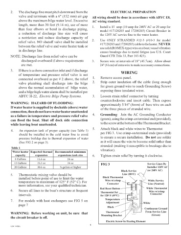
as a failure in temperature and pressure relief valve 4. Grounding: Join the AC Grounding Conductor
can flood the boat. Shut off dock side connection (green), using the crimp-on terminal end (provided),
while leaving boat unattended. to the screw at the bottom of the Thermostat Bracket.
5. Attach black and white wires to Thermostat
4. An expansion tank of proper capacity (see Table 1)
should be installed in the cold water line to avoid per FIG 3. Use crimp-on terminal ends (provided)
pressure buildup due to thermal expansion of water to ensure a secure installation. Do not use solder
(See FIG 2 on page 3). as it will cause the wire to become solid rather than
stranded (making it susceptible to breakage due to
Table 1 vibration).
Water heater Expected thermal Recommended minimum
capacity expansion expansions tank size 6. Tighten strain relief by turning it clockwise.
6 Gallons 11.6 oz 24 oz
12 Gallons 23.2 oz 24 oz FIG 3 Service Lines By
20 Gallons 38.6 oz ½ gallon or higher Installer 120V AC
Black Service (or 240V AC)
5. Thermostatic mixing valve should be Line (HOT)
installed before point of use to limit the water Black Thermostat
temperature to maximum of 125° F (52° C). For Wire w/crimp White Service
more information, see your qualified technician. Connector Line (Neutral)
6. Secure all lines to the boat’s structure at frequent Red Reset Button White Thermostat
Wire w/crimp
Thermostat Set
intervals. for 120 F (49°C) Connector
o
7. For models with heat exchangers see FIG 5 on Temperature
Adjustment
page 7 White
Black Continuous Ground
WARNING: Before working on unit, be sure that Thermostat From Service Line
(Green)
the circuit breaker is off. Mounting Bracket
4 Electric Screw-In Heating Element
4
L206 0420jlc