
Page 6 - Raritan SeaEra QC Owners Manual L365v0320
P. 6
INSTALLATION
Parts Included Mounting In-Line Strainer
All Complete Toilets (Seawater Models Only)
Toilet Bowl Make sure strainer bowl is tight.
Seat and Cover 1. Locate strainer where it will be accessible.
Lower Base Assembly 2. Mark and drill mounting holes.
Motor Cover NOTE: Hole size will depend on type of bolts/screws used
1 1/2 (38mm) 90° Discharge fitting (1/4” [6mm] size bolts/screws are recommended).
Adapter, 1” FPT x Barb 3. Install fittings provided (PLA14) on strainer’s inlet and
Control outlet ports.
Sea Water Model NOTE: Use thread sealant.
Intake Pump 4. Mount strainer. Hoses must be installed according to flow
3/4” Hose Barb - straight fitting (2) marking on strainer top.
3/4” Hose Barb - 90° fitting
Plug Fitting Mounting Remote Intake Pump
Tools Required (Remote Pump Models Only)
• 5/16” nut driver, wrench or screw driver. 1. Remote intake pump must be mounted on a flat solid surface
• 5/8” (16mm) drill bit, bit for drilling mounting surface, in an area that is dry and well ventilated.
wire cutters, wire terminal crimpers, hose cutters, tape 2. Mark and drill mounting holes.
measure. NOTE: Hole size will depend on type of bolts/screws used
Additional Parts Required 1 /4” [6mm] size bolts/screws are recommended).
• Four stainless steel mounting bolts or lag screws 3. Mount pump. Do not over tighten bolts.
(minimum 1/4” [6mm]) and washers.
• 1” (25mm) or 1 1/2” (38mm) I.D. discharge hose. FIG 1
• 3/4” (19mm) for seawater models or 1/2” (13mm)
for freshwater models, reinforced intake hose.
• Hose clamps (two for each connection below
waterline).
• Wire.
• Terminals.
• Fuse/circuit breaker.
Mounting Toilet
Mounting surface must be flat and solid.
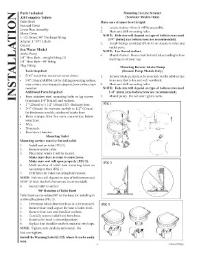
1. Install seat on toilet (FIG 1).
2. Remove motor cover.
3. Place toilet where it will be located.
Make sure there is room to route hoses.
Make sure seat will open properly (FIG 2). FIG 2
4. Mark location of toilet base mounting holes on
mounting surface (FIG 1).
5. Drill holes for toilet mounting bolts/screws.
NOTE: Hole size will depend on type of bolt/screws used
(5/16” [8 mm] size bolts/screws are recommended).
6. Secure toilet to surface
90° Rotation of Toilet Bowl
Toilet bowl can be rotated 90° on the base, for installing in
confined locations (FIG 3).
1. Determine which direction bowl is to be mounted. FIG 3
2. Remove four vinyl caps at the base of toilet bowl.
3. Remove four nuts and shoulder washers.
4. Carefully remove toilet bowl from base.
5. Rotate toilet bowl to desired position.
6. Replace four shoulder washers, nuts and vinyl caps.
NOTE: Tighten nuts carefully and evenly. Do
Not over tighten.
Install the Warning Label (L322) where it can be easily
seen.
6 L365v0320jlc